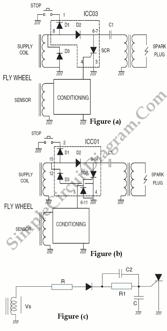
A capacitor discharge ignition works by passing an electrical current over a capacitor. A 2uf capacitor is charged to about 340 volts and the discharge is controlled by an scr.

Efficiency Optimized Fuel Supply Strategy Of Aircraft Engine
.jpg)
Ebook Pldworld Com Mirroring Jttechonline Com Circuits

Cx Wiring Diagram Honda Cx And Gl Wiki
Cdi ignition schematic circuit diagram.

Capacitor discharge ignition circuit schematic. Referring to the above capacitor discharge ignition circuit diagram we see a simple configuration consisting of a few diodes resistors a scr and a single high voltage capacitor. Each time the switch points in the distributor open it fires an scr to dump the capacitorss charge into. This type of ignition builds up a charge quickly.
These three circuits show the three types of ignition circuit. Capacitor discharge ignition cdi or thyristor ignition is a type of automotive electronic ignition system which is widely used in outboard motors motorcycles lawn mowers chainsaws small engines turbine powered aircraft and some carsit was originally developed to overcome the long charging times associated with high inductance coils used in inductive discharge ignition idi systems. Capacitor discharge ignition system working principle a cdi system.
A cdi ignition starts by generating a charge and storing it up before sending it out to the spark plug in order to ignite the engine. How to test and repair motorcycle cdi electronic ignition module coil system spark failure. The basics how capacitors work working principle.
Capacitor discharge ignition system. Fig1a is the original points based system. From my recollection it delivers a nastier spark than the legendary ford model t ignition coil.
In cdi system also called as capacitor discharge ignition system a capacitor is charged by a power source and then discharged through the primary coil of ignition coil so that high voltage is. The input to the cdi unit is derived from two sources of the alternator. Cdi capacitor discharge ignition circuit demo.
Fig1b shows a typical cdi system which uses a dc to dc inverter to charge a capacitor which typically has a value of luf. Cdi ignition schematic circuit diagram. Ad blocker detected.
The cdi ignition circuit produces a spark from an ignition coil by discharging a capacitor across the primary of the coil. The circuit uses an inverted 555 oscillator that is coupled to an on semiconductor bu323z darlington transistor 350v 10a that drives a conventional inductive discharge ignition coil. Of course open up the existing cdi capacitive discharge ignition unit and modify it but since this is completely encased in potting compound this is not something we would recommend.
Capacitor c1 stores the electrical energy and is. This ignition coil driver is a hot one.

Figure1 Schematic Of A Capacitance Discharge Ignition Cdi

Capacitive Discharge Ignition Diagram

Capacitor Discharge Scr Ignition System

Evo Ignition Schematic Wiring Diagram

Cdi Capacitor Discharge Ignition Circuit Demo Youtube

براءة الاختراع Us20050205073 Supplemental Capacitive
Below Is A Schematic Of A Typical Scooter Electrical Set Up

Cdi Ignition Schematic Wiring Schematic Diagram 147

Race Engines Ignition System Diagram Wiring Diagram

Chevrolet Silverado 1500 Questions Rear Brake Lights Not
Capacitive Discharge Ignition Exciter Using Scr Discharge
Capacitive Discharge Ignition Diagram
Comments
Post a Comment